Related posts:
Yaesu FT290 yet a very good ham radio rig suffers from a leaky screen which is a natural phenomenon touching soon or late every transceiver of this generation.
In this article, I propose a replacement alternative that is based on the latest OLED technology offering an average lifespan of 30000 hours.
The history started with my FT-290 which needed the screen to be replaced. Looking on the internet for brand new replacement parts I discovered that not match at all information exists on the subject. The only interesting source was found on the ZS1KE website where the author build its own version of the display based on the Arduino microcontroller and describes the communication protocol used by the transceiver to send the info to the original screen which was of great help for me.
Unfortunately, no contact information of ZS1KE was found, nor any shop where his display can be purchased, I decided to develop my own variant.
The architecture was based on the ST microelectronics microcontroller (MCU) which was acting as a translator between FT-290 data protocol and the OLED screen base on the SSD1306 controller.
First of all, for development purposes, the FT-290 was replaced by an FPGA board which was more or less an emulator able to provide screen data in a good shape and format equal to those sent by the transceiver. As for the MCU, a Nucleo evaluation board was taken.
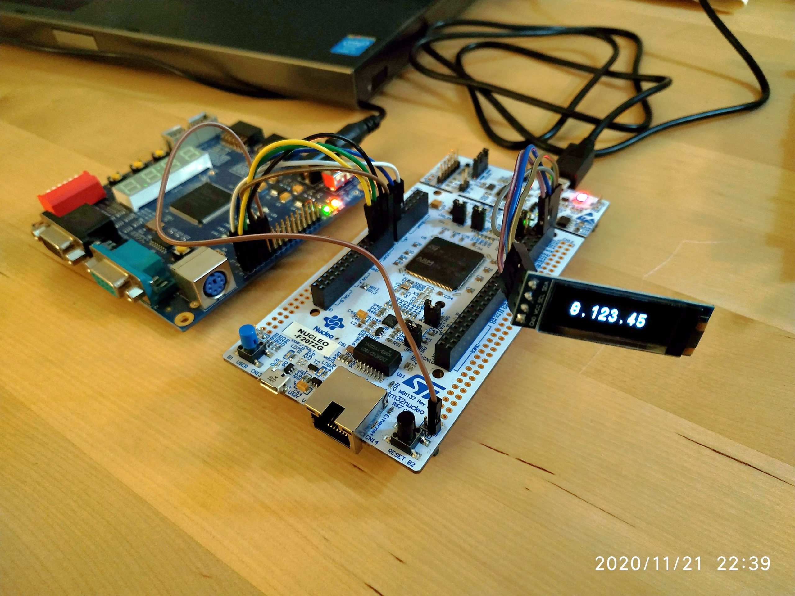
Using a couple of buttons on the FPGA board I was able to increase and decrease numbers shown on the OLED. This was a big validation step.
Once the Nucleo board can intercept the data from the pseudo rig and send the information to the OLED, I could replace the FPGA board with the FT-290 to see if it works!
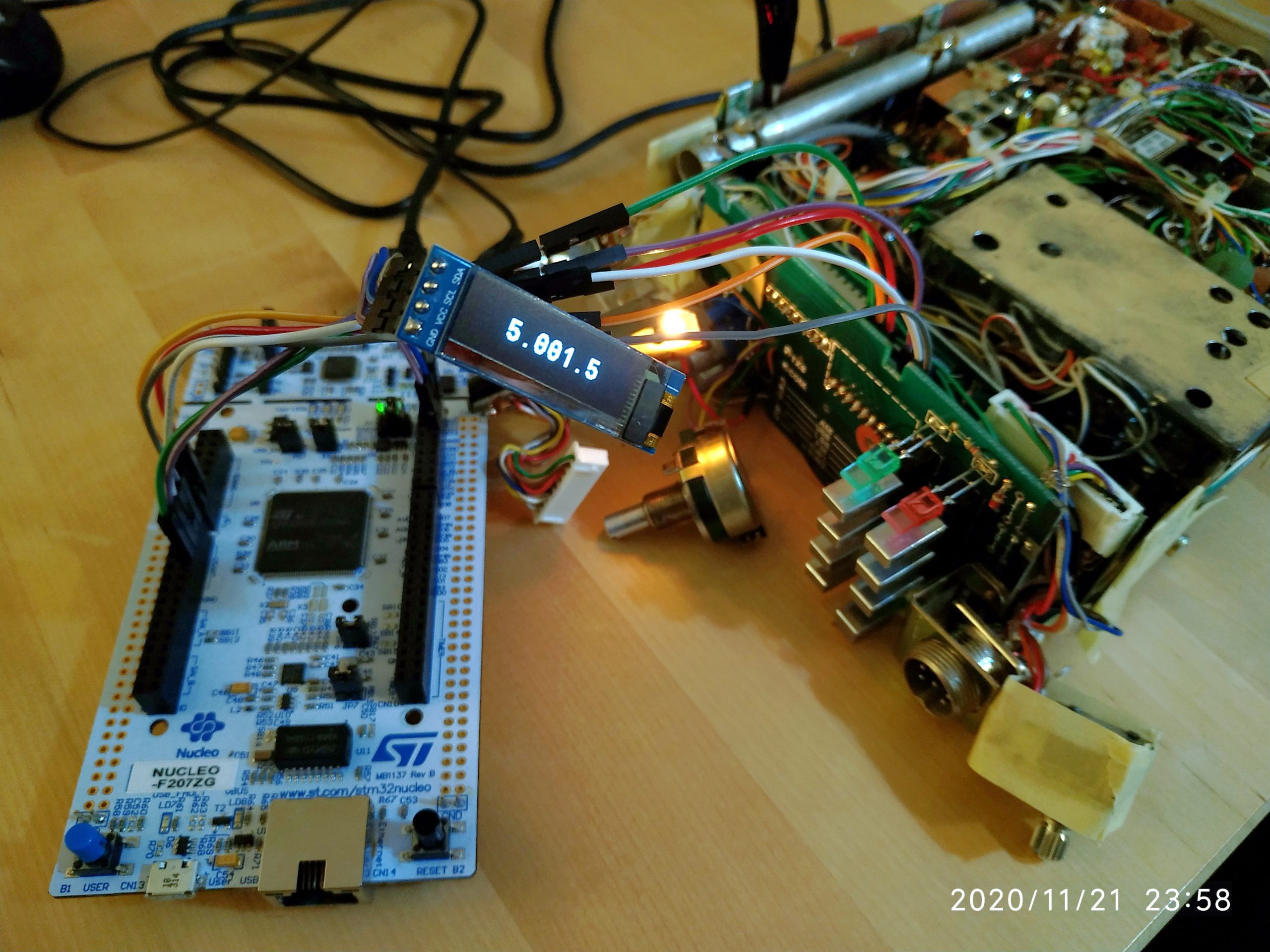
After another couple of hours, the OLED was finally able to show the frequency of the transceiver which was 145.001.5 MHz. And of course, this was not static, the frequency was changing almost by miracle when the rotary encoder of the rig was actioned.
The only thing to do was the integration of the OLED into a small place inside of the FT-290. For this purpose, the Nucleo board was replaced with a custom PCB holding a small STM32F103 controller and a couple of resistors.
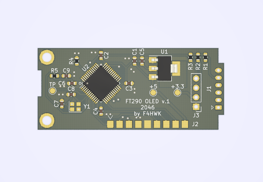
At this stage, the regulator was initially designed to be supplied with +5V from one of the wires of the ribbon JST connector. However, this voltage was not able to produce enough current to power the OLED and the MCU in my case. Maybe some further investigations should be done. In the meanwhile, the power was migrated to the +12V line also available in the rig. The closest one was directly connected to the old screen to supply the backlight lamp.
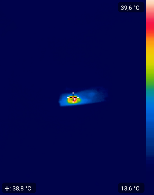
Since the power supply was migrated to the +12V line, the temperature of the +3.3V regulator U1 should be checked and the power consumption evaluated. Depending on the percentage of use of the OLED matrix, the current draw varies from 40 to 70 mA. The temperature of the regulator, in this case, is close to 40 °C which is good.
The dimensions of this PCB were carefully designed to be equal to those of the original screen and thus avoid any mounting problems. The position of the OLED screen was also adjusted to fit at its best the window in the plastic cover.

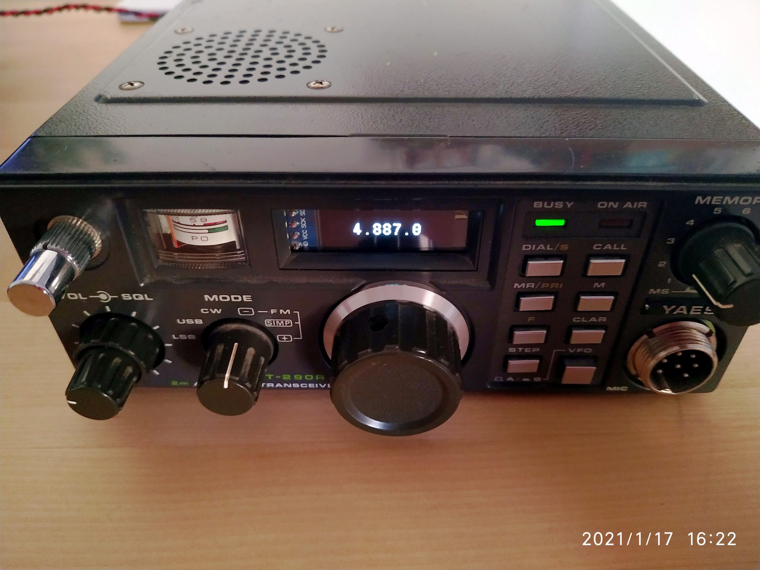
Once everything is assembled back the rig is alive again with a good and clear display showing the frequency but also all other functions like CLAR, Memory, etc.
This OLED module is available on ebay from f4hwk-fr (myself), where you can ask me for any questions.